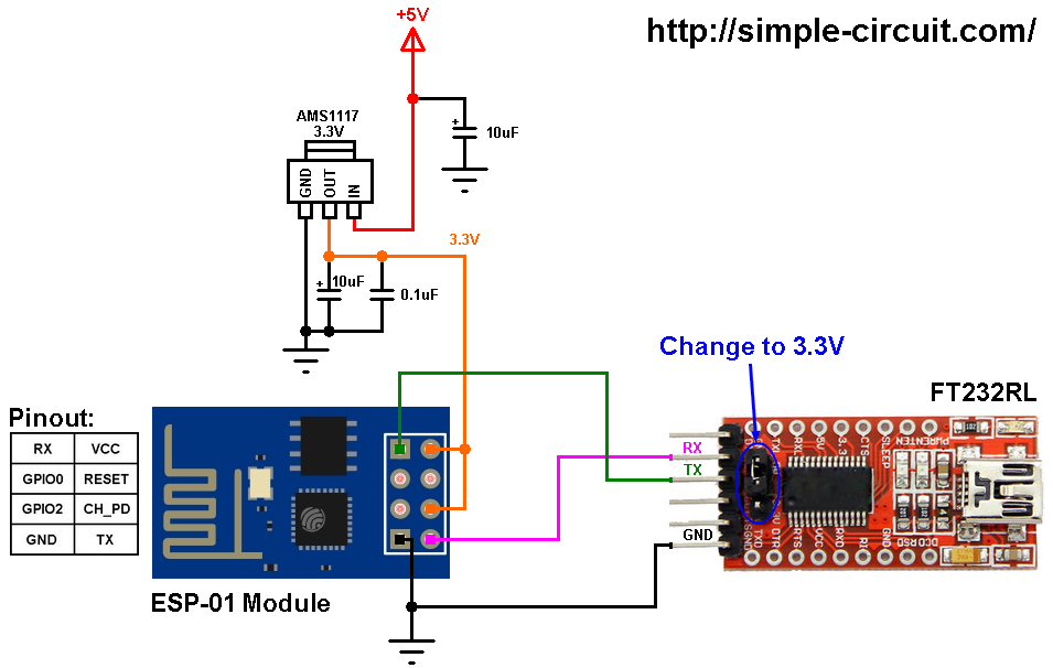
Esp8266 01 Projects Series Presently Includes
The ESP8266 series presently includes the ESP8266EX and ESP8285 chips. With the same speed engineers work hard to reduce the size of every electronic device or component and loose most of the wiring.The ESP8266 series, or family, of Wi-Fi chips is produced by Espressif Systems, a fabless semiconductor company operating out of Shanghai, China. Technology goes ahead exponentially with each year whether we do something or not. ESP8266 Arduino tutorial – WiFi module complete review. It may not have the QIO/QOUT pads routed to the flash chip. Connect your ESP8266-01 Module to PC 2.Open your Arduino IDE 3.Go to File -> Preferences 4.Add this link to Additional Board Manager 5.Go to Tools -> Board Manager 6.Find ESP8266 board set and activate it 7.Select Generic ESP8266 board from Tools->Boards 8.Choose your programmer COM port 9.You are ready to goThis is a great option if your project does not have enough memory or.


Esp8266 01 Projects Code In The
8.4.1 Master SI / SPI Control (Optional) The master serial interface (SI) can operate in two, three or four-wire bus configurations to control the EEPROM or other I2C/SPI devices. The ESP8266 contains several analog and digital interfaces described in the following sections. Wow wow wow so much hw stuff with buffer is there an beginner code in the pipe best wishes rudi - Time for start isr example. i think i did sleep in this phase - honest did not saw that we have no existing ( working ) i2c slave standalone example again in esp-idf likewise we did not haved in esp8266.
...
Circuit is powered through the same power that we apply to vcc of esp8266 module. A 470 ohm resistor is connected in series to led. I choose GPIO-2 because GPIO-1 is used during uploading code. Esp8266-01 has only two GPIO’s(General Purpose Input Output Pins) GPIO-0 amd GPIO-2.
NodeMCU is an open source IoT platform that includes firmware which runs on the low cost Wi-Fi enabled ESP8266 Wi-Fi SoC from Espressif Systems. In this tutorial we will interface OLED Display with NodeMCU ESP8266. You could have at the max 8 of these multiplexers connected together on 0x70-0x77 addresses in order to control 64 of the same I2C addressed parts. The channels are selected by sending the TCA9548A its I2C address (0x70 - 0x77) followed by the channel number (0b00000001 - 0b10000000).


 0 kommentar(er)
